


TriStar MPPT 600V Solar controller
Model and rating
TriStar MPPT 600V has two models
TS-MPPT-60-600V-48
Maximum 60 ampere charging current for battery.
DC system voltage 48V
PV input DC voltage maximum 600V
Communication includes RS-232, EIA-485, MeterBusTM, and Ethernet.
TS-MPPT-60-600V-48-DB
Maximum 60 ampere charging current for battery.
DC system voltage 48V
PV input DC voltage maximum 600V
Main characteristics
The name and characteristics of each part of the TriStar MPPT 600V-48 model controller are shown in Figure 2-1 below.
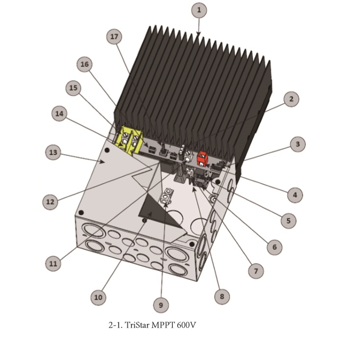
1 – heat radiators from the aluminum radiator help the controller to discharge the heat from the work (in view of reliability, TriStar MPPT 600V is designed to be 100% passive heat dissipation).
2 – LED indicator 3 power charge LED indicator shows charge status and controller failure.
3 - dial setting switch and 8 dial setting switch for different configuration of TriStar MPPT 600V.
4 – positive pole connection (red) battery positive pole connector.
5 - MeterBusTM interface RJ-11 MorningStar for general purpose MeterBusTM networking
6 -- RJ-45 block for Ethernet interface LAN and Ethernet interface.
7 - RS-232 serial interface 9 pin series interface (concave)
8 - EIA-485 interface for EIA-485 communication 4 bit connector
9 - earth terminal (2) grounding of the controller housing.
10 – blank instrument cover (fixed with 4 screws) optional digital display screen (model: TS-M-2-600V) mounting cover.
11 - battery negative connection terminal battery negative connection connector.
12 - remote temperature sensor connector and morning star (MorningStar) remote temperature sensor (RTS) to monitor battery temperature connections.
13 - the cover of the junction box to protect the power connector.
14 – photovoltaic terminal bridge (yellow) is used to isolate PV terminal high voltage and low voltage connection areas.
15 - photovoltaic junction terminal PV positive and negative pole power connector
16 – battery voltage induction connector to accurately measure battery voltage connections.
17 - button switch manually reset faults or errors, also used for manual on / off balance.
The name and characteristics of each part of the TriStar MPPT 600V-48-DB model controller are shown in Figure 2-2 below.
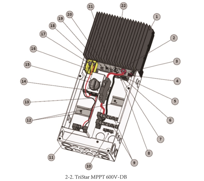
1 – heat radiators from the aluminum radiator help the controller to discharge the heat from the work (in view of reliability, TriStar MPPT 600V is designed to be 100% passive heat dissipation).
2 - battery negative pole power connector, battery cable negative terminal power connector.
3 - battery positive power supply connector (red) power connector of battery cable positive terminal
4 - dial setting switch and 8 dial setting switch for different configuration of TriStar MPPT 600V-DB.
5 - MeterBusTM interface RJ-11 MorningStar for general purpose MeterBusTM networking
6 -- RJ-45 block for Ethernet interface LAN and Ethernet interface.
7 - RS-232 serial interface 9 pin series interface (concave)
8 - EIA-485 interface for EIA-485 communication 4 bit connector
9 – battery connections are used to connect the positive and negative poles of the battery.
10 - earth wire joint system earthing connection head
11 - Photovoltaic terminal wiring board (showing 1) for power supply of PV positive and negative electrodes
12 - auxiliary DIN Guide
13 - isolation point of battery positive pole of battery circuit breaker
14 - earth wire joint system earthing connection head
15 - isolating switch for PV terminal isolator
16 – photovoltaic terminal bridge (yellow) is used to isolate PV terminal high voltage and low voltage connection areas.
17 - Photovoltaic negative electrode power connector has been connected to the PV negative extreme cable connection point.
18 - Photovoltaic positive electrode power supply connector has been connected to the PV extreme cable connection point.
19 – battery voltage induction connector to accurately measure battery voltage connections.
20 - button switch manually reset faults or errors, also used for manual on / off balance.
21 - remote temperature sensor connector and morning star (MorningStar) remote temperature sensor (RTS) to monitor battery temperature connections.
22 – LED indicator 3 power charge LED indicator shows charge status and controller failure.
 WeChat
 RSS
RSS